Raspberry Pi GPIO Sensors to MQTT
30 October, 2020
What it is
Though it may have been a mistake, my wife agreed to let me build us a home security system instead of buying one. I say mistake, because that was just over a year ago & we still don't have a complete system installed (to be fair, we've had a lot going on). I've finally had the time to work on this project again recently, so I've started by reviewing what I built last December before our son was born. This part of the system is a seemingly simple one: install & handle the sensors, then communicate their status to the necessary consumers.
A first attempt
It worked great, except when it didn't
When we bought the house, it was set up already with a wireless (345 Mhz RF) system from Honeywell that required third party monitoring. My first idea was to reuse the existing sensors to save money (& it was theoretically going to be quicker), although I was wary of RF wireless systems' glaring security flaws. Using a software defined radio (I used the RTL-SDR V3) & Joel Fuster's HoneywellSecurityMQTT I eventually put together something that worked. Except for one problem: it didn't actually work. Or to be more accurate, it worked a lot of the time, but would unpredictably & silently stop communicating with the sensors & require a manual reboot at least once a day, which kind of made it useless.
An actual solution
A user configurable and extensible python application that runs in Docker on a Raspberry Pi and reads GPIO input from sensors, then broadcasts via MQTT
So with that first idea scrapped, I set out to make a new system using new sensors (reusing some parts of the Honeywell sensors, such as the reed switches in the door sensors) & a new networking method. This time, I went with a wired design (to prevent the RF jamming/interference issues mentioned above) using a Raspberry Pi as the controller. Additionally, I wanted this system to maintain the decentralized nature of the failed RTL-SDR attempt, so I decided to design it as a series of microservices, capable of running on one or multiple devices, starting with one for broadcasting the sensor events via MQTT.
In the end, built something that does the following:
- A sensor is wired into a Raspberry Pi's GPIO pins
- A python script uses RPi.GPIO to listen to the pins, then send the appropriate message via MQTT
- The same python script also monitors the system for errors & shutdown events & broadcasts healthy/fault status via MQTT
- Runs in Docker so as to avoid python environment conflicts & ease user setup & installation
Currently, I'm using HomeAssistant to monitor the sensors via MQTT, then handle any events via its built-in automations tools. My next step is to create a standalone service can be given arm status levels (i.e. disarmed, perimeter only armed, fully armed), then monitors the sensors and acts according to its armed status.
How it works
The source code is available on GitHub, along with documentation on wiring sensor circuitry, installing the software, & running the application, but I'll give a quick run-down of how it works here.
Sensor wiring
I'm using two types of sensors for now: Form A (Normally Open, SPST) reed switches & HC-SR501 PIR motion sensors. Each one has fairly different wiring requirements, so I'll break it into two parts.
1. PIR motion sensor
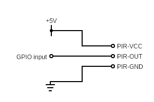
The HC-SR501 PIR has 3 pins & is fairly simple to hook up. You just need to run a jumper from a +5V power pin (# 2 or 4) to the PIR-VCC pin, then from PIR-GND to any one of the ground pins (#s 6, 9, 14, 20, 25, 30, 34, or 39), & lastly one more from the PIR-OUT to any one of the non power or ground pins (make sure to take note of which pin for configuration).
2. Form A reed switch
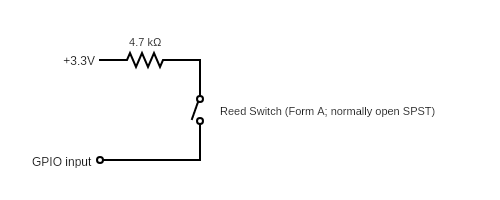
A normally open single pole, single throw reed switch is only a little more complex than wiring a PIR sensor. A resistor is needed to protect the Pi from any possible shorts (but wiring a hardware pull-down or pull-up circuit is not required as the Pi's software version on the Broadcom chip is used instead). To wire this sensor, connect the 3.3 Volt pin (# 1) to a lead on a resistor (anything from 1k to 5k Ohms should work), then connect the other lead to a lead on the Reed Switch. Lastly, connect the other Reed Switch lead to any open GPIO pin.
Docker stuff
The Dockerfile is fairly straightforward, with only a couple items of interest:
- Because building on a Pi Zero is so slow, I've set it up to use QEMU to
allow it to be built on an x86 machine while targeting an ARM processor. This
is achieved by a
post_checkoutDocker hook that downloads QEMU's ARM release, then unpacks the tarball & moves it so that the Dockerfile can copy it ondocker run. - While the user configuration file,
configuration.yaml, is copied ondocker run, the recommended run command includes setting up a Docker volume that allows the user to replace it with their own & edit it without having to rebuild the entire image.
Sensor handling
Coding this part was where things got interesting (although, I actually hadn't used a soldering iron or built any circuits in years, so wiring the sensors was pretty fun for me). I built the application as a set of independent, functional (mostly functional, that is, two are just wrappers on the imperative GPIO & MQTT libraries used) modules all wired together in one imperative Application class.
Listening to the GPIO pins starts with
RPi.GPIO. Using it involves a bit of a
setup process & that process depends on knowing what pins you're using & if
they need any special properties (i.e. a software pull-up or pull-down
circuit). To avoid making a mess of the application, I separated the config
concerns from setting up the GPIO pins by creating a wrapper class around
RPi.GPIO that dynamically handles the setup process using a given list of
sensors.
# gpio.py

import RPi.GPIO as io

class GpioHelper:
    def __init__(self, sensors_list: dict):
        if not sensors_list:
            raise ValueError(
                "At least one sensor must be given"
            )

        self.__pins = []
        io.setmode(io.BCM)

        for (pin, sensor) in sensors_list.items():
            self.__pins.append(pin)

            if sensor.pull_up or sensor.pull_down:
                if sensor.pull_up:
                    pull_up_down = io.PUD_UP
                elif sensor.pull_down:
                    pull_up_down = io.PUD_DOWN

                io.setup(
                    pin,
                    io.IN,
                    pull_up_down=pull_up_down
                )
            else:
                io.setup(pin, io.IN)
After setting up the pins, we still need a way to start (& stop) listening for
changes. Stopping listening is as simple as calling RPi.GPIO's cleanup() to
free up the pins. Starting listening, however, is a little more involved,
requiring iterating over each pin set up in __init__() & adding an event
detection callback to it on both UP & DOWN events.
# gpio.py

from typing import Callableimport RPi.GPIO as io

from src import utils # just a simple utility class for logging
class GpioHelper:
    def __init__(self, sensors_list: dict):
        # ...

    def start_listening(self, callback: Callable[[int], bool]):
        for pin in self.__pins:            utils.log(                "Adding GPIO listener on {pin}".format(pin=pin)            )            io.add_event_detect(pin, io.BOTH, callback=callback)

            utils.log("Waiting for motion detection")

    @staticmethod
    def stop_listening():
        utils.log("Quitting motion detection...")
        io.cleanup()
        utils.log("GPIO event detection stopped & cleaned")
Getting the list of sensors to pass to GpioHelper's __init__ is a matter of
loading the users config file & parsing it into a list of some sort of sensor
objects. This is done by opening the file & parsing it using the os & yaml
packages, then passing the resulting dict into Configs where the sensors are
iterated over & built into Sensor instances using the module's build_sensor
method.
# configs.py

import os
import yaml

from src import sensors

class Configs:  # pylint: disable=too-few-public-methods
    def __init__(self, config_obj: dict):
        self.sensor_list = {}

        for (group, sensor_list) in config_obj['sensor_groups'].items():
            for sensor in sensor_list:
                sensor['group'] = group
                self.sensor_list[sensor['pin']] = sensors.build_sensor(sensor)


def load_configs(config_file: str) -> Configs:
    with open(config_file, 'r') as stream:
        return Configs(yaml.safe_load(stream))
Of course, building that sensor_list takes a Sensor class. For my purposes,
a sensor needs to know information about itself to be published (such as a
name, type, & group), in addition to its GPIO pin number. Additionally, a
sensor needs to be able to find its current state, and some sensors may need a
pull-up or pull-down software circuit to work correctly (such as a reed
switch).
This is actually a great case for class inheritance, so we'll start with a base
Sensor class that all the sensor types (such as MotionSensor &
ReedSwitch) will inherit from.
# sensors.py

class Sensor:
    def __init__(self, data: dict):
        self.pin = data['pin']  # type: int

    def determine_state(
        self,
        check_state_callback: Callable[[int], bool]) -> str:

        return "TRIPPED" if check_state_callback(self.pin) else "OK"

    @property
    def pull_up(self):
        """Read-only attribute, tells if sensor requires pull
        up resistor.
        """

        return False

    @property
    def pull_down(self):
        """Read-only attribute, tells if sensor requires pull
        down resistor.
        """

        return False


class MotionSensor(Sensor):
    """Subclass of Sensor, for HC-SR501 type PIR sensors.

    Currently has no different behavior from Sensor.
    """


class ReedSwitch(Sensor):
    """Subclass of Sensor, for basic door/window reed switches.

    Differs from Sensor in two ways:
    1. Returns 'OK' where the Sensor would return
       'TRIPPED' & vice-versa
    2. Requires a pull up resistor
    """

    def determine_state(self, check_state_callback):
        """See Sensor.determine_state."""
        return "OK" if check_state_callback(self.pin) else "TRIPPED"

    @property
    def pull_down(self):
        """See Sensor.pull_down."""
        return True
Lastly, sensors needs the build_sensor helper used by configs. It reads
the dictionary received from configs & builds 'motion' types as MotionSensor
& 'door' & 'window' types as ReedSwitch.
# ...

def build_sensor(sensor: dict) -> Type[Sensor]:
    sensor_type = sensor.get('type', 'default')
    sensor['type'] = sensor_type if sensor_type is not None else 'default'
    types = {
        'motion': MotionSensor,
        'door': ReedSwitch,
        'window': ReedSwitch,
    }

    return types.get(sensor['type'], Sensor)(sensor)
Hooking Configs & GpioHelper together is fairly simple: give the
configurations.yaml path to load_configs & pass the resulting dictionary's
sensor_list property to GpioHelper. Of course, that alone doesn't do
anything since GpioHelper needs to be told to start listening, then be told
when to stop. Since this app will simply either be running or not, that's
easily represented as a run & a quit method:
# app.py

#
# import dependencies
#
import time
from typing import Callable

from src import utils
from src.configs import load_configs
from src.gpio import GpioHelper


class App:
    def __init__(self):
        # load configuration
        self.__configs = load_configs('/app/configuration.yaml')

        # setup GPIO pins
        self.__gpio = GpioHelper(self.__configs.sensor_list)

    def run(self):
        def __cb(pin_returned):
            return self.__event_detected(pin_returned)

        self.__gpio.start_listening(__cb)

        while not self.__exit:
            time.sleep(600)

    def quit(self):
        # cleanup
        self.__gpio.stop_listening()
        utils.log("rpi-pir2mqtt successfully shut down")

        raise SystemExit

    def __event_detected(self, pin_returned):
        sensor = self.__configs.sensor_list[pin_returned]

        # ...  more to be done here with reading sensor state
        #      & publishing MQTT messages
With the above, sensors are actually being monitored with a callback that's executed any time an event is detected—the only problem being, the callback currently does nothing. The goal here is to broadcast sensor events via MQTT, so I wrote a (thoroughly uninteresting) helper to to establish a connection using a given host & port, end that connection, & publish messages.
The last part needed to get a bare minimum working application (with no error
handling, fault signaling, etc.) is that the sensor state needs to be read on
event detection so that it can be included with the message being published.
To do this, one last method needs added to GpioHelper:
# gpio.py

class GpioHelper:
    # ...

    @staticmethod
    def input(pin_no: int) -> bool:
        """Wrap & directly expose RPi.GPIO's input method."""
        return io.input(pin_no)
Which is then called in App.__event_detected:
# app.py

class App:
    # ...

    def __event_detected(self, pin_returned):
        sensor = self.__configs.sensor_list[pin_returned]
        state = sensor.determine_state(self.__gpio.input)

        # .. send the mqtt message
Finally, the app can be run by initializing an App instance, assigning
listeners to call App.quit() on SIGINT, SIGTERM, & on Exceptions:
# app.py

import time
import signalfrom typing import Callable

# ...

def sig_handler(signum: int, _frame) -> None:    utils.log(        "sig_handler processing {signum} signal"        .format(signum=signum))    APP.quit()APP = App()signal.signal(signal.SIGTERM, sig_handler)signal.signal(signal.SIGINT, sig_handler)try:    utils.log("Starting app...")    APP.run()except Exception as err:  # pylint: disable=broad-except    utils.log("Exception caught in final try...except block.")    APP.quit()
With that, app.py just needs to be given executable permissions, then it'll
work. The full version includes more robust error handling along with
abstractions on what an Event is (used when publishing MQTT messages &
outputting to logs). The source code is available
on GitHub.
~~~
Do you have any questions or comments about anything? I'd love to hear from you! Send me a message using the form or any of the social media platforms below, or just send me an email at hello@andrew-chang-dewitt.dev